Industrial-grade precision spring contacts engineered for high current capacity, magnetic coupling systems, and board-to-board interconnect interfaces.
Pogo pins, or spring-loaded electrical contacts, represent a cornerstone of modern electronics manufacturing. Because they provide dynamic electrical connections that accommodate misalignments, vibration, and thousands of mating cycles, they are widely integrated into consumer electronics, testing jigs, high-speed interfaces, and industrial power couplings. However, a pogo pin is only as reliable as its mounting configuration. Incorrect mounting leads to off-axis plunger wear, PCB delamination, micro-disconnections, and reflow damage. Choosing the right physical configuration and mounting process ensures optimal contact force, low contact resistance, and a lifetime of robust electrical signal integrity.
Depending on spatial constraints, assembly throughput, and current handling profiles, design engineers select one of three main technical mounting profiles. We break down the execution steps, layout tolerances, and process considerations for each below.
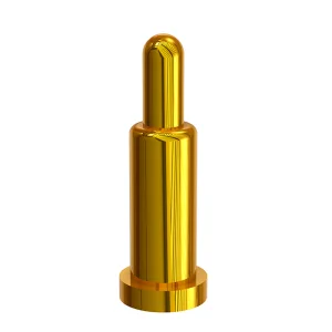
The plunger is designed with a flat bottom barrel or a locating peg, designed for automated high-volume pick-and-place assembly. Offers excellent space savings and low assembly cost but lower mechanical shear resistance than through-hole styles.
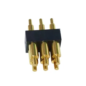
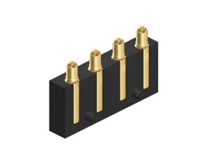
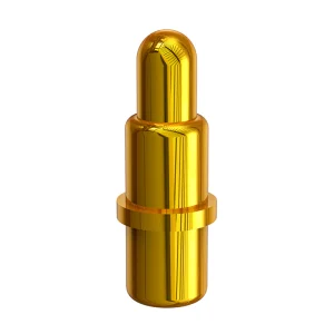
The tail of the pogo pin penetrates the PCB layer. Solder flows through the plated through-holes to establish a highly robust anchor. Best choice for high-insertion-force devices and high-current paths where thermal dissipation is critical.
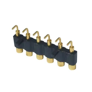
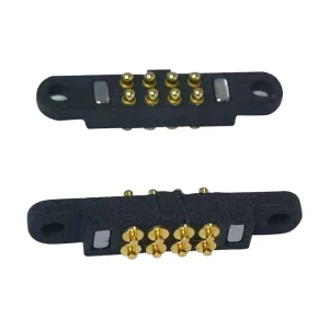
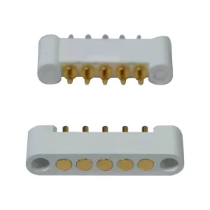
Ideal for edge connectors and smart docks. The tail is formed at a 90-degree angle, or the barrel is configured with a horizontal contact direction. Prevents force vector from transferring directly downwards onto SMT solder joints.
Use this reference table to evaluate mounting styles according to key engineering limits:
| Mounting Method | Typical Pitch Limit | Current Rating | Mechanical Durability | Reflow / Wave Temp Peak |
|---|---|---|---|---|
| Surface Mount (SMT) | ≥ 1.0 mm | Up to 5A / Pin | Moderate (dependent on solder pad size) | 260°C (Lead-Free SAC305) |
| Through-Hole (DIP) | ≥ 1.57 mm | Up to 15A / Pin | High (reinforced mechanical bond) | 245°C - 260°C |
| Right-Angle / Bending | ≥ 2.0 mm | Up to 3A / Pin | High (shear stress decoupled) | 255°C |
| Floating / Wire-Solder | N/A (Housing bound) | Customized per wire gauge | Excellent (independent of PCB) | Manual Solder / Wire Crimp |
SMT is the most common integration method in contemporary consumer electronic production lines (like TWS charging docks or smartwatches). Follow this technological sequence to guarantee high coplanarity and eliminate solder-wicking issues:
Ensure the stencil thickness is selected between 0.10mm and 0.15mm. The stencil opening should be designed to yield 90-100% paste coverage on the copper pad to prevent starvation, yet avoid bridging with neighboring pins.
Pogo pins must have flat caps (disposable polyimide caps or molded heads) to allow vacuum suction nozzles to grab them. Ensure component nozzle height target is calibrated to compress the pin plunger by no more than 0.1mm during pickup.
Do not exceed the melting temperature of internal springs (typically copper or music wire alloys). Keep peak reflow zone time (250°C to 260°C) strictly within 30-40 seconds. Excess heating degrades internal lubricant coatings and compromises tension.
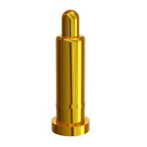
Capillary action can draw liquid solder paste up inside the barrel, sealing the plunger shut. Select pogo pins designed with pre-applied solder-barrier bands or anti-wicking bottom caps, preventing solder from rising above the base plane.
Pogo pins must be adapted to different localized environmental stresses. Below, we look at four specialized applications where custom-mounted pogo configurations excel.
Mounted inside tight plastic housings, pogo pins must support dynamic human movement. Gold-plating thicknesses are optimized to 30u" to withstand human sweat, sebum corrosion, and environmental humidity. Pin designs often use waterproof housings with custom-molded silicone gaskets.
Subjected to persistent mechanical vibration, automotive pogo pins use side-mounted bending architectures to isolate connection interfaces from vibration vectors, preventing contact chatter. High-durability stainless-steel springs deliver reliable contact under thermomechanical cycles.
Medical sensors require stable impedance and biocompatibility. Our custom spring loaded contacts are built using premium gold-on-nickel or palladium-nickel (Pd-Ni) multi-layer plating, providing low-noise transmission even after thousands of wipe cycles.
For global OEMs and design agencies, sourcing electronic components involves balancing production speed, customization capabilities, and rigorous quality verification. Operating in the heart of Songgang Street, Shenzhen—a leading hub of the Guangdong-Hong Kong-Macao Greater Bay Area—Shenzhen Rongqiangbin Electronic Hardware Co., Ltd. offers unparalleled manufacturing advantages:
Founded in February 2011, Rongqiangbin has focused on design and mass manufacturing of premium Pogopin connectors for over a decade. We control the complete process: from precision high-speed Swiss CNC machining and automatic spring winding to environmental plating checks and automated camera inspections. This vertical integration allows us to deliver high-quality custom pogo pins with short leads times and reliable quality control.
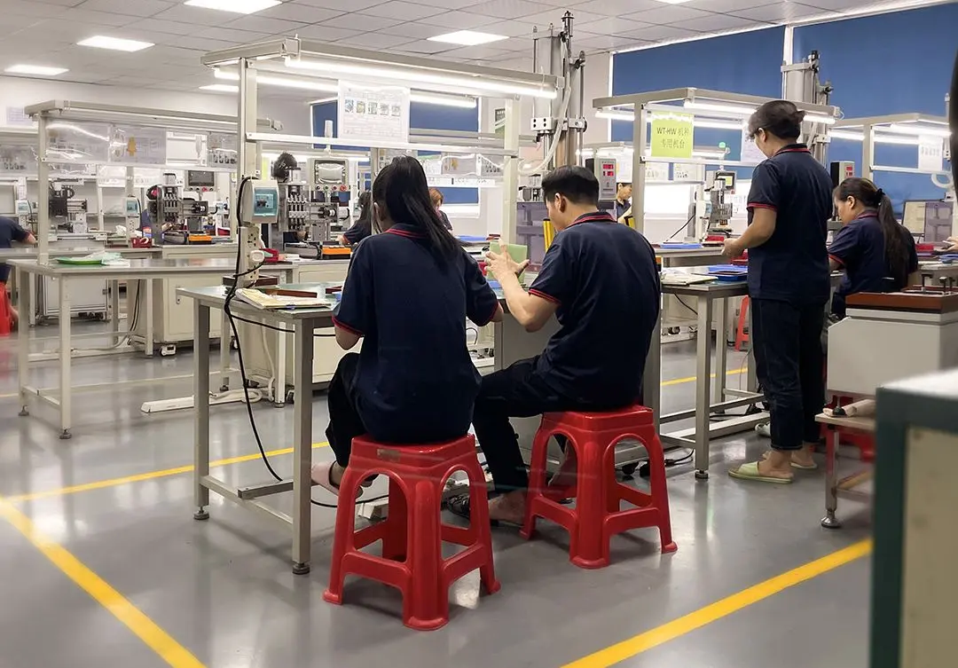
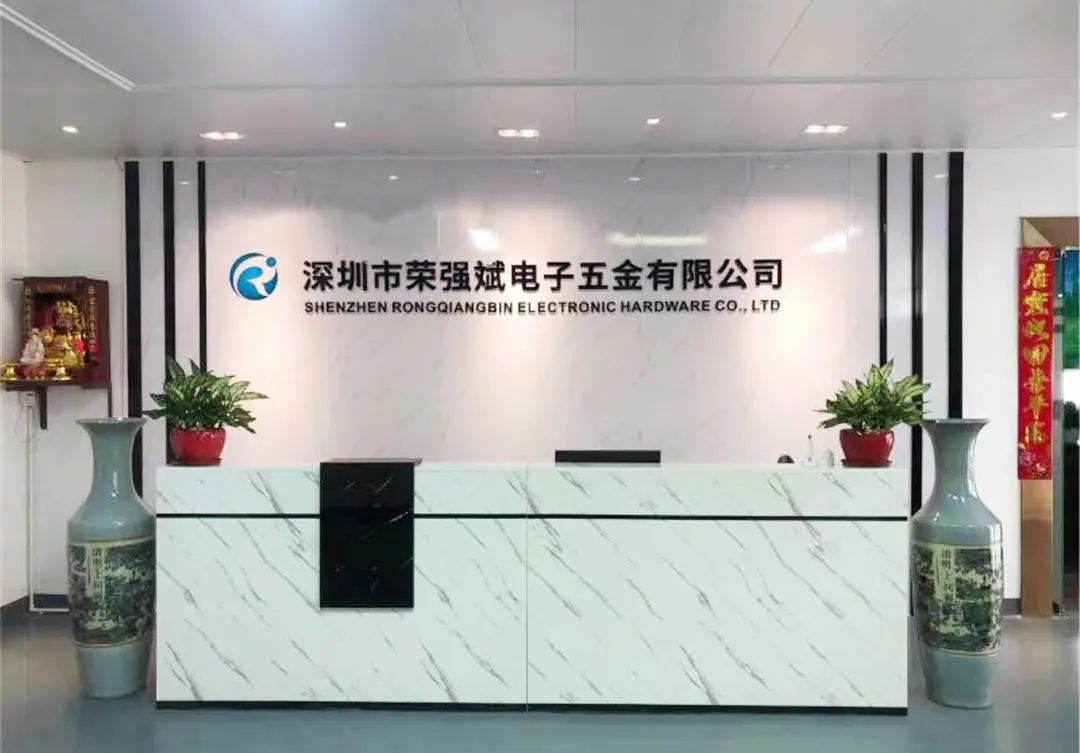

We are ISO9001:2015 certified, establishing robust inspection points at every stage of production. From raw material incoming quality control (IQC) through in-process checks (IPQC) to 100% final inspections (FQC), we verify mechanical and electrical stability. Every batch is matched to full trace codes to secure reliable performance in high-stress end environments.

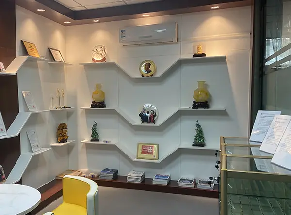
Rongqiangbin's focus on quality, cost-performance, and delivery has established long-term relationships with global industry leaders:
As electronic systems demand higher speeds, denser component pitches, and larger current capacities, traditional contact methods face physical limits. The industry is evolving across three core vectors:
Next-generation wearable AR/VR devices require terminal spacings down to 0.4mm pitch. Traditional barrels are replacing solid-turn brass bodies with ultra-thin electroformed sleeves, utilizing precision micro-springs to match space limits while maintaining adequate spring force.
Modern charging ports do more than supply power—they carry gigabit data. High-speed pogo pin configurations are designed using controlled-impedance lines (typically 50-ohm or 90-ohm differential signals) to match USB4 or PCIe Gen5/6 requirements, reducing signal loss and reflections.
Fast charging introduces high currents (10A to 40A) across small contacts. Custom plating, such as palladium-doped gold alloys, combined with internal ball designs (bias-cut plunger structures), reduces contact resistance, minimizing thermal buildup at the interface.
Common design, processing, and application questions answered by Rongqiangbin's application engineering team.
A: Always specify high-temperature housing materials (such as LCP or PA9T plastics) when ordering pogo pin arrays. Limit the peak reflow temperature to 260°C for no more than 40 seconds. If necessary, use wave shielding or Kapton stickers during manufacturing to protect the dynamic plunger assemblies from heat and flux residues.
A: We recommend operating pogo pins at 2/3 of their maximum travel capacity. Compressing the pin to its mechanical stop can overload the spring and shorten its lifecycle. Conversely, operating at less than 1/3 travel risks intermittent connections due to environmental vibrations or board tolerance variations.
A: Design the contact plunger with a biased-cut tail or insert an internal ball between the plunger and the spring. This pushes the plunger against the inner barrel wall, creating a direct electrical path that bypasses the high-impedance spring coil.
A: Pogo pins are designed for axial compression. Side forces create friction against the barrel, which accelerates wear and can cause sticking. If your design requires side force, use right-angle bending types, incorporate protective physical alignment features into the housing, or select a side-mounted model.
A: We use high-precision plastic injection molds and automated assembly fixtures. Our automated optical inspection (AOI) systems measure the alignment and height of each pin terminal. This ensures coplanarity stays within a strict ≤0.1mm tolerance, ensuring reliable solder joints across all pads.
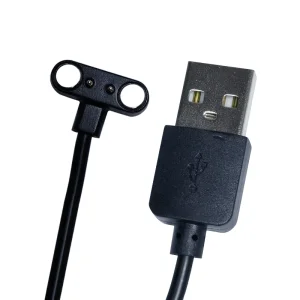
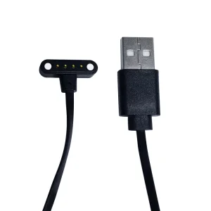
Explore our collection of side-mount connectors, waterproof interfaces, SMT spring pins, and custom magnetic cables.
 Rongqiangbin Electronic