Explore our premium spring-loaded connector solutions designed for custom wiring, surface mounting, and demanding industrial applications.
A masterclass in termination styles, thermal dynamics, and reliable electrical integration for spring-loaded pins.
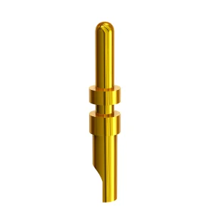
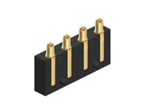
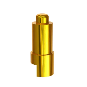
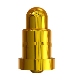
Proper termination is critical to electrical integrity. When wiring pogo pins, options include solder cups for harness attachments, surface mount (SMT/SMD) tails for direct automated board integration, and through-hole (DIP) tails for mechanical strength on heavy boards. Selecting the tail structure ensures solid strain relief and minimum impedance.
Internal springs inside pogo pins are highly heat-sensitive. High temperatures (exceeding 260°C for more than 3 seconds) can cause annealing in stainless steel or copper alloy springs, permanently degrading contact force. Safe hand-soldering requires controlled lead-free temperatures (320°C max) and rapid contact dwell times.
During the wiring of pogo pins with cables, solder flux can capillary up the plunger gap if too much solder is applied. This causes the plunger to freeze, resulting in a failed open circuit. Apply minimal, precise amounts of RMA flux or use pre-tinned conductors to ensure zero vertical flow into the spring cavity.
1. Wire Preparation: Strip high-flexibility, fine-gauge wire (such as 26-30 AWG silicone wire) to an exposure length matching the solder cup depth, typically 0.8mm to 1.2mm.
2. Tinning: Lightly tin both the stripped wire tip and the solder cup of the pogo pin using lead-free SAC305 solder. Ensure a bright, smooth finish.
3. Mechanical Fixture: Fix the pogo pin housing in a thermal-insulating jig. Do not exert clamping force directly on the barrel wall, which could crush the internal assembly.
4. Controlled Heat Application: Touch the pre-tinned wire to the cup. Apply heat from a chisel tip iron for no longer than 1.5 to 2.5 seconds. Pull back heat immediately once reflow is achieved.
5. Strain Relief & Encapsulation: Pogo pins are designed for compression, not lateral shear forces. Protect the wired end with low-pressure overmolding (LPM) or custom epoxy potting to distribute mechanical strain.
| Wiring Method | Typical Applications | Pros | Cons / Design Constraints |
|---|---|---|---|
| Solder Cup Tail | Wire-to-Board, Cable Harnesses | Excellent mechanical pull strength, high reliability in rugged environments. | Requires precise manual soldering or semi-automated solder fixtures. |
| SMT/SMD Reflow | High-volume Consumer PCBs, TWS Charging Cases | 100% automated Pick-and-Place, low assembly cost, high component density. | Limited mechanical shear strength, requires accurate planar pad alignment. |
| Through-Hole (DIP) | Heavy Industrial Equipment, Power Units | Superior mechanical anchoring, resistant to severe insertion forces. | Requires PCB routing space on both layers, wave-soldering processes. |
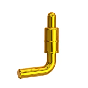
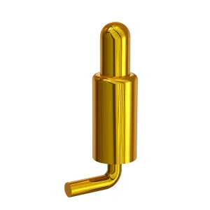
| Bending & Right-Angle | Compact Smart Wearables, Keyboards | Extremely low profile, side-mating options for tight chassis spaces. | Complex design parameters, fragile structure during manufacturing handling. |
How cutting-edge hardware design requirements are shaping the engineering and manufacturing of spring-loaded contacts.
With consumer devices getting thinner, the pitch distance between wired pogo pins has shriveled from the standard 2.54mm down to 0.5mm and below. This necessitates microscopic wire termination techniques, laser wire stripping, and micro-precision injection-molded carriers to prevent bridging.
Fast-charging systems, industrial robotics, and new energy vehicle battery connections demand pins capable of carrying 10A to 40A continuously. Standard pogo pins overheat under such currents. The industry trend uses solid-core ball designs, biased plungers, and advanced copper alloys to minimize contact resistance.
Wearables exposed to sweat and water suffer from galvanic corrosion. The future of pogo pins relies on specialized biocompatible coatings like platinum, palladium-nickel (Pd-Ni), and proprietary multi-layer gold plating to withstand up to 1 million cycles without high impedance build-up.
Evaluating vendor capabilities, volume scalability, and risk management strategies for OEM/ODM hardware brands.
For procurement directors at top-tier consumer electronics, medical device, and automotive companies, selecting a pogo pin factory extends far beyond unit costs. Reliability metrics dictate the entire operational lifecycle of the product.
The primary procurement demands center on statistical process control (Cpk ≥ 1.33), raw material traceability, environmental compliance certifications, and fast-turn prototyping capabilities for iterative product design phases.
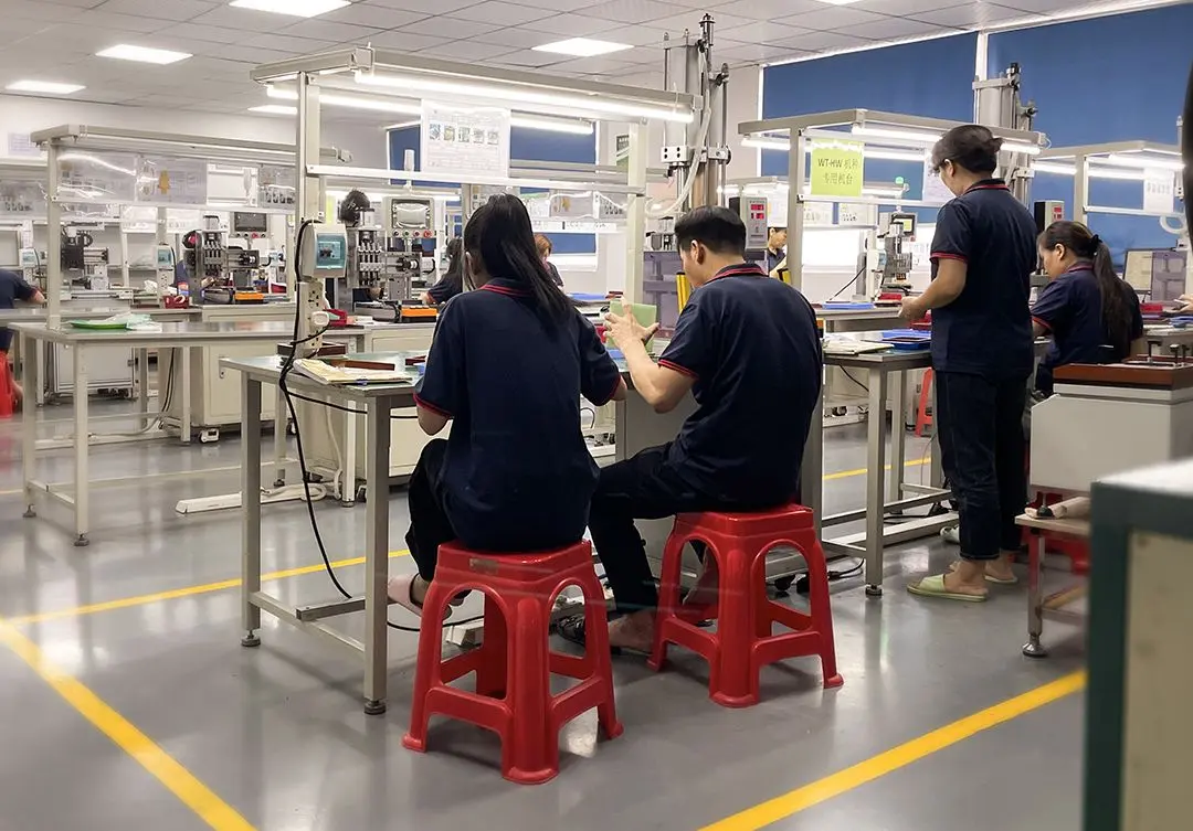

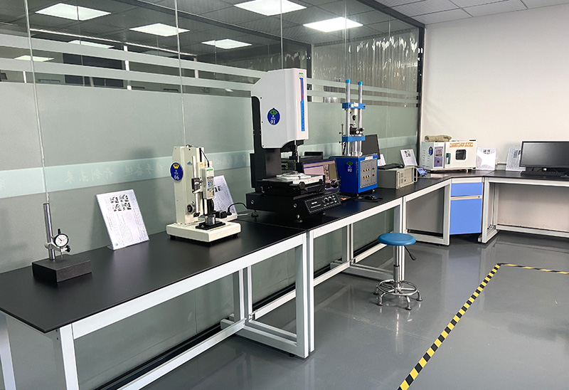
Ensuring constant spring force over 100k+ compression cycles. High-precision dynamic force-displacement curve testers verify consistent performance.
Resistance must remain under 30 milliohms throughout the lifespan to prevent excessive voltage drop and high-temperature points on the PCB.
100% automated optical inspection systems filter out microscopic deformities, spring misalignments, or surface plating scratches before shipping.
A premier industry leader specializing in high-performance ODM & OEM pogo pin connectors.
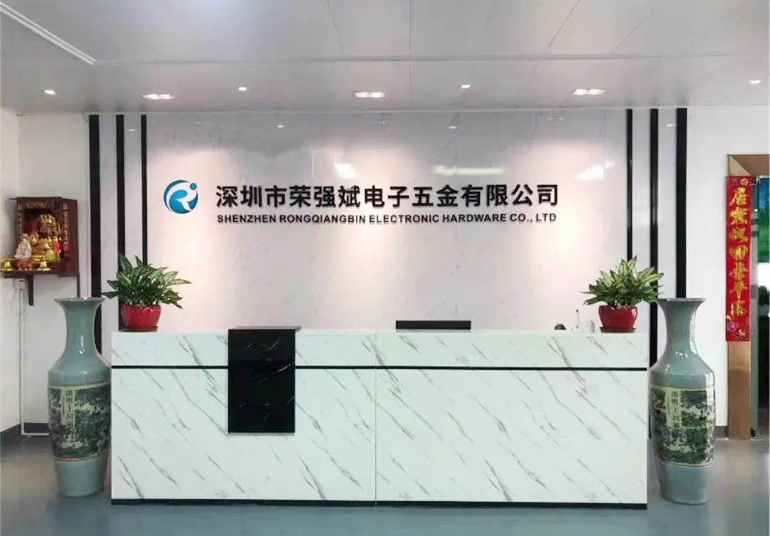
Shenzhen Rongqiangbin Electronic Hardware Co., Ltd. is located in Shenzhen, the leading city of the Guangdong-Hong Kong-Macao Greater Bay Area. Our company was founded in February 2011 in Songgang Street, Shenzhen, specializing in the development and manufacturing of Pogopin connectors. After years of efforts and sedimentation, the company gradually became a leader in the industry.
Our company’s spirit of "customer first, integrity first" principle has built a strong POGO PIN industry technology production team, establishing long-term cooperative relationships with a number of global enterprises. We have obtained the ISO9001:2015 version of the international authoritative quality management system certification, supported by a strong quality management team and strict environmental management systems to provide customers with all kinds of high quality and environmentally friendly products.
10+ Years manufacturing experience with 4000+ clients and 300+ patents.
Perfect system certification and advanced testing equipment.
100% inspection during production fulfillment and before shipping.
Fast delivery and excellent after-sales support.

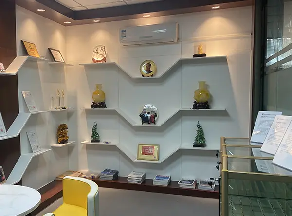
Committed to being excellent POGO PIN manufacturers for both quality and cost at home and abroad, and leading connector technology development.
We establish strategic hardware supply partnerships with leading multinational firms including:

Tailored electrical contact architectures across medical, automotive, aerospace, and consumer electronics verticals.
Medical electronics demand stable bio-compatibility, low contact resistance, and water-tightness. Custom-wired pogo pin arrays equipped with silicone O-rings provide hermetic seals up to IPX8 waterproof rating, essential for surgical equipment sterilizers and patient monitoring units.
With the rise of Autonomous Driving (ADAS) and EVs, sensor pods, battery-monitoring arrays, and charging ports require rugged spring contacts that resist engine bay vibrations. Heavy-duty through-hole wiring combined with thick brass barrels ensures continuous contact without micro-interruptions.
IC testing labs and circuit board assembly lines require millions of actuation cycles. We construct high-durability test probes using hard gold over nickel barriers to ensure that resistance curves remain flat across extreme heat and mechanical cycle tests.
Adhering to strict international standards for green manufacturing, conflict-free mineral sourcing, and global logistics.
All pogo pin components (barrels, plungers, and springs) are manufactured strictly in compliance with RoHS 3 and REACH regulations. We implement mercury, lead, and cadmium-free processes across all brass turning and plating lines.
Our quality management workflow follows ISO standards strictly from raw brass wire extrusion checks, precision CNC lathe tolerances, through automatic spring insertion assembly, to the final packaging stage.
We provide localized engineering consults for companies in the USA, Europe, and Asia-Pacific. From mechanical tolerance simulation to PCB layout design assistance, our team speeds up your time-to-market.
Anticipating the demands of the next decade with pioneering engineering and material innovations.
Developing ultra-low-friction carbon coatings over precious metal platings to eliminate gold erosion during continuous sliding contacts in robotic interfaces.
Pioneering coaxial pogo pins with dedicated dielectric sleeves to support data transfer speeds up to 20 Gbps for high-speed automated test operations.
Improving intelligent magnetic charging interfaces with high blind-mating tolerance to protect pogo pins from side-shear damage in industrial docking bays.
Expert engineering answers to critical design questions concerning spring-loaded connection systems.
It is not recommended. Pogo pins consist of independent dynamic plungers, barrels, and springs. Without a rigid structural carrier (typically PPS, LCP, or PBT plastics), the pins can tilt under compression, causing mechanical binding and loss of contact. A precise housing keeps the pins parallel to the mating surface.
The internal spring is typically made of stainless steel (SUS) or beryllium copper (BeCu) wire. Excessive soldering temperature or dwelling the iron on the pin for too long will trigger annealing. This alters the crystal structure of the metal, dramatically decreasing the spring force, causing contact degradation and intermittent signals.
For standard solder cups, wire gauges between 24 AWG and 30 AWG are ideal. Using wires that are too thick will act as a heat sink, requiring longer reflow times and risking internal spring damage. Wires that are too thin might lack the mechanical shear strength needed for long-term usage.
Waterproofing is achieved by combining three structural methodologies: using silicone O-rings around individual pin barrels, implementing low-pressure overmolding (LPM) encapsulating the entire wire connection block, or applying potting resins (epoxies or polyurethanes) to form a physical barrier at the rear exit of the connector.
This is typically caused by solder flux wicking back into the barrel during assembly, which leaves a thin insulating coating on the spring or plunger interfaces. Alternatively, it can occur due to inadequate plating thickness on the plunger, or oxidation resulting from excessive heat application that damages the gold plating layers.
Yes, provided they are supported by a rugged housing. Bent tails are useful for low-profile layouts. However, under high vibrations, the spring force must be designed higher (typically 80g to 150g) to prevent contact bounce. The wire harness attached to the tail must have proper stress relief loops to prevent force transfers to the solder joints.
Discover our specialized spring-loaded pin categories including magnetic, custom high-current, and keyboard interfaces.
 Rongqiangbin Electronic