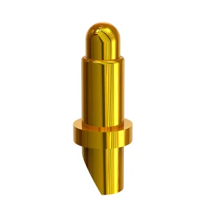
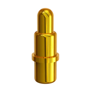
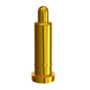
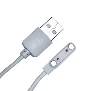
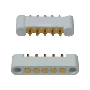
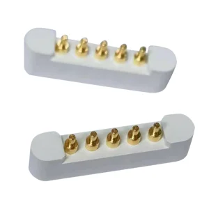
Explore our industrial-grade OEM/ODM pogo pin systems engineered for high durability and optimal conductivity.
Understanding mounting styles, mechanical tolerances, and thermal constraints during assembly processes.
For high-density PCB layouts, SMT is the preferred installation methodology. When assembling Mill-Max style pogo pins, proper pad size geometry is critical to prevent shifting during reflow. Solder paste thickness must be precisely controlled (typically 4 to 6 mils) to guarantee stable coplanarity.
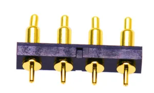
For applications experiencing high mechanical stress or structural loading, through-hole (DIP) mounting is ideal. Plated through-holes (PTH) anchor the pin's tail, providing exceptional resistance to shear forces and mating pressure.
| Mounting Method | Typical Applications | Key Tolerance Spec | Recommended Solder Profile | Durability Rating |
|---|---|---|---|---|
| SMT (Surface Mount) | Consumer Electronics, Ultra-thin Wearables | ±0.03mm Coplanarity | Lead-Free Reflow Peak 245°C | Up to 1,000,000 Cycles |
| DIP (Through-Hole) | Industrial Docking, Testing Fixtures | +0.05mm Hole Dia. | Wave Solder 255°C (3-5s contact) | Excellent Shear Strength |
| Press-Fit (Solderless) | Automotive Systems, Reworkable Modules | ±0.015mm Hole Dia. | No Solder (Mechanical Force) | Moderate Assembly Cost |
How to design mating interfaces to prevent premature pogo pin fatigue and electrical failures.
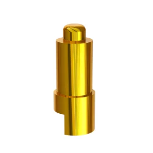
Never compress a pogo pin to its solid state. The optimal working stroke is 50% to 70% of the maximum travel distance. Over-compression causes stress fractures in the internal micro-springs, degrading electrical performance.
Pogo pins are engineered for axial force application only. Lateral or shearing force on the plunger causes frictional wear on the barrel edges, leading to physical sticking, plating wear, and contact resistance spikes.
Mill-Max style connectors require gold plating (typically 10u" to 50u" over Nickel) to prevent oxidization. Maintain target board surface pads with a minimum of 15u" gold to ensure stable electrical transmission and zero oxidation.
Why worldwide OEMs and procurement teams rely on Shenzhen Rongqiangbin for customized spring pin designs.
Global procurement offices face challenges matching standard catalogs to specialized designs. Space limits in small devices, high current loads, and harsh environments require customized geometries. This is where ODM and OEM partnerships excel.
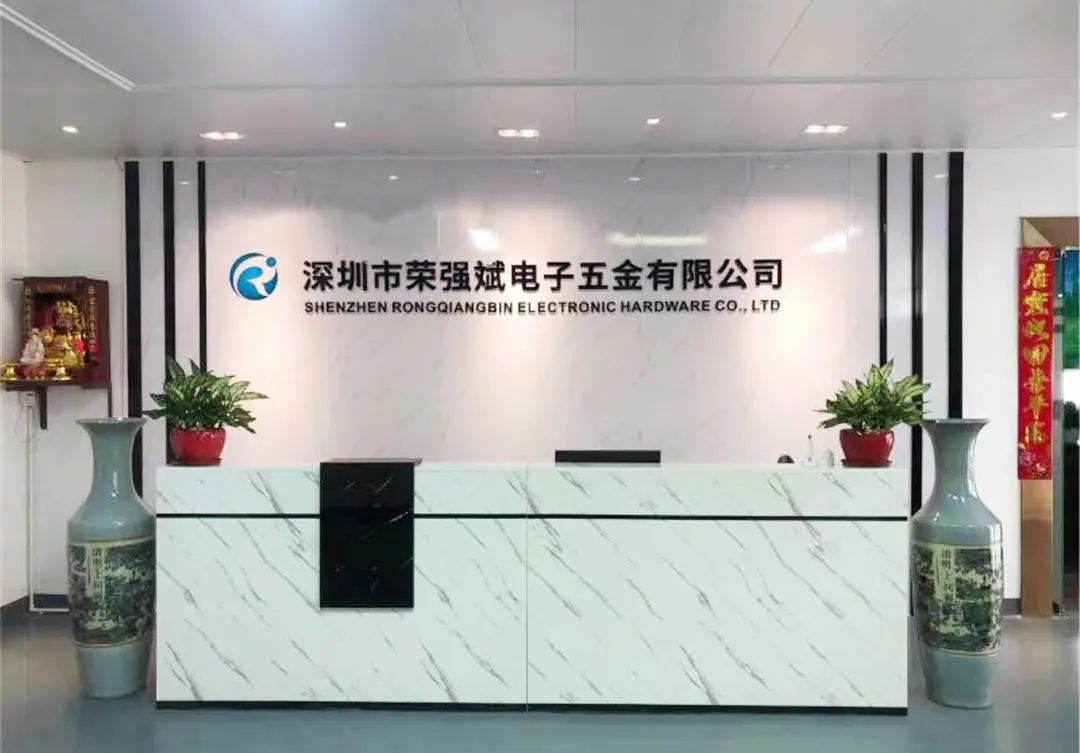
As a leading Chinese manufacturer, Shenzhen Rongqiangbin Electronic Hardware Co., Ltd. (founded in February 2011 in Songgang Street, Shenzhen) specializes in designing and manufacturing pogo pin systems tailored to precise dimensional, current, and environmental requirements.
Customization Scope:
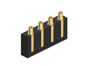
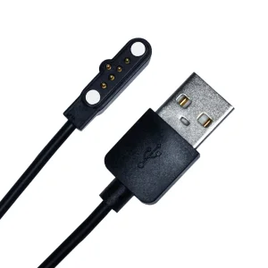
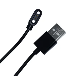
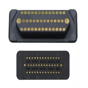
We modify barrel lengths, spring rates, plunger profiles, and plating stackups. We manufacture customized magnetic cable assemblies, multi-row connectors, and side-mounted pin layouts for complex PCBs.
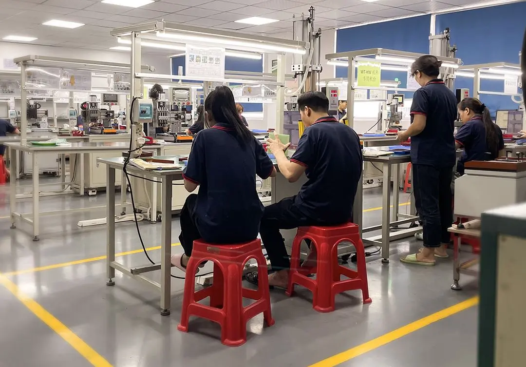

The evolution of high-speed transmission, high-current charging, and ultra-miniature architectures.
With smart wearables and IoT nodes shrinking, pogo pin pitch dimensions have dropped to 1.0mm or smaller. High-density design requires ultra-low profile pins (under 1.5mm) that can still deliver at least 0.5A stable current.
Fast-charging paradigms demand contacts that can carry 5A to 15A continuous current without thermal runaway. Advanced internal design features, such as bias-cut plungers or ball-inserted barrels, ensure lower contact resistance.
Wearables must withstand sweat, dust, and water. Integrating pogo pins with O-rings, overmolding, or waterproof epoxy sealants allows designers to achieve reliable IPX7 or IPX8 systems, protecting internal circuitry.
A pioneer in precision hardware and spring-loaded connector technology since 2011.
Shenzhen Rongqiangbin Electronic Hardware Co., Ltd. is located in Shenzhen, the leading city of the Guangdong-Hong Kong-Macao Greater Bay Area. Our company was founded in February 2011 in Songgang Street, Shenzhen, specializing in the development and manufacturing of Pogopin connectors. After years of effort and development, the company has become a leader in the industry.
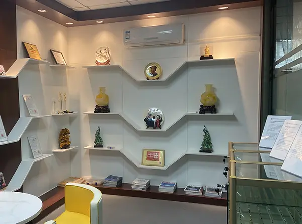
Our company’s spirit follows the principle of "customer first, integrity first." Supported by a strong production team in the POGO PIN industry, we have established long-term partnerships with numerous enterprises. We have obtained the ISO9001:2015 international quality management system certification, maintaining a strict quality management team and environmental management system to deliver high-quality, environmentally compliant products.
We are proud to serve global industry leaders and well-known brands, including:
How we ensure zero defects in multi-million volume production runs of pogo pin connectors.
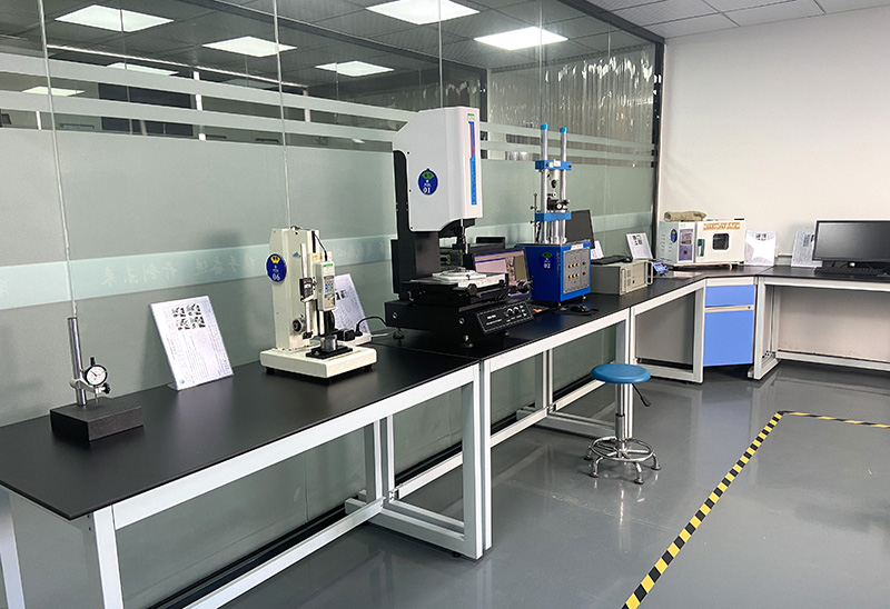
Our facility is equipped with high-precision testing machinery to verify mechanical and electrical stability. Every production batch undergoes strict evaluation to confirm compliance with global standards.
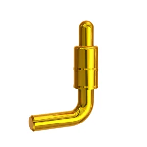
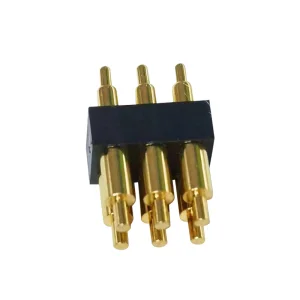
We invest continuously in R&D to improve assembly yields for challenging designs, such as high-density multi-row connectors and right-angle pogo pin arrays.
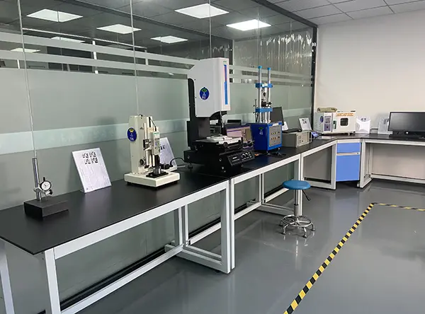

Our commitment to advancing pogo pin technology for next-generation electronics.
Developing nickel-free plating finishes to prevent skin allergies in wearable devices and medical equipment, while improving overall salt water resistance.
Using custom cobalt-copper alloy springs and optimized internal guide components to extend operational life beyond standard limits for industrial test sockets.
Co-axial pogo pin designs that route gigahertz RF signals along with high-current power in a single hybrid connector system.
Direct technical answers from our engineering department regarding installation, design, and sourcing queries.
Browse our catalog of custom SMT, DIP, magnetic connectors, and multi-row socket arrangements.
 Rongqiangbin Electronic